Elecrow ThinkNode M9
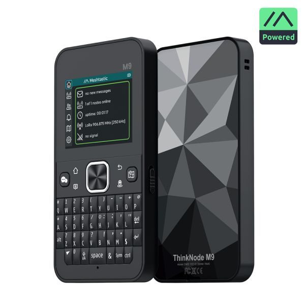
The first board here whose radio is not a Semtech SX12xx. The LR1110 is a new family (RadioLib LR11x0) and the reason this board took the work it did: it drives its own antenna switch from its own DIO lines, and until it is told which line means what in each mode it answers over SPI, reports a firmware version, accepts a channel and transmits into a pin that goes nowhere — online by every measure this firmware has, and silent. So the radio is declared by the board rather than probed for, and the switch table lives in the board header. Its bandwidth list is four steps below 1 GHz where the SX126x has ten, so a channel carried over in NVS from another board is corrected at boot rather than failing the probe. Two more firsts: the peripheral rail is active low here (the T-Deck's is active high), and the chip's own USB pins are spent on the panel and the keyboard bus, so the USB pad is released at boot and the console is the CH340 bridge on UART0. No touch layer at all — the shell is driven from the keyboard, which is what the keypad group is for.
01 Hardware
| Vendor | Elecrow |
| PlatformIO env | thinknode-m9 |
| Board header | src/boards/thinknode_m9.h |
| MCU | ESP32-S3: 16 MB flash, 8 MB octal PSRAM in package |
| Chip family | ESP32-S3 |
| Radio | Semtech LR1110 (TCXO at 3.3 V, the chip drives its own antenna switch from DIO5/DIO6) |
| Display | 2.4" 320x240 ST7789, no touch layer |
| Extras | full keyboard on its own microcontroller (I2C, register-addressed) with six shortcut keys wired to the shell's screens, ATGM336H GNSS, microSD, sounder, PCF8563 RTC, QMI8658 IMU, QMC6309 magnetometer, 2300 mAh cell behind an LGS4056 charger; PPP over the CH340 bridge |
| Host links | Wi-Fi access point + station · CH340 serial bridge · PPP over that bridge |
| Flashing | esptool can reset the chip through this port |
02 Radio
| Transceiver | Semtech LR1110 |
| Radio family | LR11xx |
| As the registry states it | Semtech LR1110 (TCXO at 3.3 V, the chip drives its own antenna switch from DIO5/DIO6) |
| TCXO | 3.3 V reference |
| DIO2 drives the RF switch | no |
| Default channel | 869.525 MHz · BW 125 kHz · SF8 · CR 4/5 · 7 dBm inherited from Config.h |
| SPI bus | FSPI — shared with the panel and the card slot |
Every node on a channel must agree on frequency, bandwidth, spreading factor,
coding rate and sync word. These are the defaults this build ships with; they are changed
live on the node's settings page, which prints the matching RNodeInterface block.
03 Pin map
Read straight out of src/boards/thinknode_m9.h — every peripheral
the firmware drives on this board, and the GPIO it drives it on. A harness diagram, not a
picture of where the parts sit.
Every pin as a table, with the define it comes from
| Peripheral | Signal | GPIO | Define | Note |
|---|---|---|---|---|
| Radio | SCK | GPIO 40 | PIN_LORA_SCK | |
| MISO | GPIO 38 | PIN_LORA_MISO | ||
| MOSI | GPIO 47 | PIN_LORA_MOSI | ||
| CS | GPIO 39 | PIN_LORA_CS | ||
| RST | GPIO 45 | PIN_LORA_RST | ||
| BUSY | GPIO 41 | PIN_LORA_BUSY | ||
| DIO1 | GPIO 42 | PIN_LORA_DIO1 | ||
| TFT panel | SCK | GPIO 40 | PIN_TFT_SCK | |
| MOSI | GPIO 47 | PIN_TFT_MOSI | ||
| MISO | GPIO 38 | PIN_TFT_MISO | ||
| CS | GPIO 16 | PIN_TFT_CS | ||
| DC | GPIO 15 | PIN_TFT_DC | ||
| RST | GPIO 14 | PIN_TFT_RST | ||
| BL | GPIO 17 | PIN_TFT_BL | ||
| Keyboard | SDA | GPIO 20 | PIN_KEYPAD_SDA | |
| SCL | GPIO 21 | PIN_KEYPAD_SCL | ||
| INT | GPIO 12 | PIN_KEYPAD_INT | ||
| BL | GPIO 46 | PIN_KEYPAD_LED | backlight, driven from this chip | |
| microSD | SCK | GPIO 40 | PIN_SD_SCK | |
| MISO | GPIO 38 | PIN_SD_MISO | ||
| MOSI | GPIO 47 | PIN_SD_MOSI | ||
| CS | GPIO 48 | PIN_SD_CS | ||
| GNSS | RX | GPIO 2 | PIN_GPS_RX | |
| TX | GPIO 3 | PIN_GPS_TX | ||
| EN | GPIO 11 | PIN_GPS_EN | ||
| RST | GPIO 5 | PIN_GPS_RST | ||
| PPS | GPIO 4 | PIN_GPS_PPS | ||
| STBY | GPIO 10 | PIN_GPS_STANDBY | high forces the receiver awake | |
| I²C bus | SDA | GPIO 7 | PIN_I2C_SDA | |
| SCL | GPIO 6 | PIN_I2C_SCL | ||
| Power | BOARD | GPIO 18 | PIN_BOARD_POWER | |
| VBAT | GPIO 13 | PIN_BATTERY_ADC | ||
| Controls & indicators | BTN | GPIO 0 | PIN_BUTTON | |
| BUZZ | GPIO 9 | PIN_BUZZER |
04 Firmware support
What this build actually drives on this board. Where a part is fitted but left alone, the firmware's own reason is quoted underneath rather than summarised.
| Capability | State | Detail |
|---|---|---|
| Reticulum transport | driven | Path table, announce propagation, hop-by-hop forwarding |
| Wi-Fi AP + captive portal | driven | Status page, neighbours, bulletin board, settings |
| TCP 4242 + AutoInterface | driven | Stock RNS clients, zero-config discovery |
| LoRa radio | driven | Semtech LR1110 |
| Radio self-test at boot | driven | Proves the IRQ line on first boot A transmit at boot, timed against the interrupt. Worth it here for the same reason as on the amplified board: a radio with an unconfigured antenna switch reports itself up and says nothing on the air |
| RF front end | no | Driven before the radio can hear anything |
| External PA | not driven | — No external amplifier: the 22 dBm ceiling is the chip's own high-power PA, which RadioLib selects by itself for anything above 14 dBm — and which the switch table above has its own row for, so the antenna follows |
| Display | driven | TFT · 240×320 A 2.4" 320x240 panel, which is a 240x320 controller mounted landscape. The part is an ST7789 and not the ILI9341 the size suggests |
| Backlight control | driven | PWM An LED behind a transistor on a PWM channel — the ordinary kind, unlike the T-Deck's one-wire dimmer — but wired so that it lights when the pin is LOW. All three sources agree, one of them by driving it low to turn it on |
| Touch layer | not driven | — No touch layer on this board at all. It is the first colour board here without one, so the shell has nothing to point with and the keyboard is the only way around it |
| Keyboard | driven | register-addressed over I²C Not the T-Deck's protocol: this one is register-addressed. Write the key register, then read one byte. It also has its own bus, away from the sensors, and brings its slave up at 100 kHz |
| Trackball | no | — |
| microSD | driven | Reticulum store moves onto the card when one is present |
| GNSS | driven | 115200 baud Both reference firmwares name these pins from the receiver's point of view in at least one place, so copying either header's names gives a dead UART. The direction below is the ESP32's: it listens on GPIO 2 |
| Real-time clock | driven | Seeds the system clock at boot A PCF8563 at 0x51, confirmed answering on this bus rather than taken from the vendor's page. It is the only board here with a clock of its own, and it is the difference between a node whose time is right at boot and one that counts from 1970 until the sky clears — see Rtc.h |
| Power management IC | no | — |
| Battery gauge | driven | — A 2:1 divider on GPIO 13, always connected. Worth knowing: GPIO 13 is ADC2 on this chip, and ADC2 is the converter the radio and Wi-Fi stack contend for — a reading here can fail while the other one is busy, which is a missed sample rather than a wrong one |
| IMU | driven | QMI8658 A QMI8658 at 0x6b and a QMC6309 at 0x7c, both read off the bus before either driver was written: WHO_AM_I 0x05 and chip id 0x90, by `I2C <addr>` on the console. The magnetometer is the heading and the accelerometer is what makes it true when the board is not held level |
| Magnetometer | driven | QMC6309 Mounting orientation, still to be settled. Inverting X was tried on the reasoning that it selects between the two side rotations and nothing else; on the bench it made every orientation wrong rather than fixing two, so the reasoning was wrong about which axis does what here. Left at the identity until the accelerometer has been read in a known pose — STATUS reports it — rather than flipped again on another guess |
| Environment sensor | no | — |
| Sounder | driven | — A sounder on a PWM channel, behind a driver transistor. Four sources name the pin. Elecrow's tables also show a GPIO 9 in the keyboard's matrix, which is a different chip's GPIO 9 and not a conflict |
| USB networking (CDC-NCM) | no | The node is an Ethernet link with DHCP over the cable |
| PPP over the serial bridge | driven | Bridge: CH340 |
05 Bench notes
verified on hardware: LR1110 online and on air (boot self-test TxDone in 7 ms through the chip's own antenna switch, and a packet received), panel, keyboard, microSD on the shared bus (15.6 GB SDHC, Reticulum store on the card), GNSS talking (308 sentences, no fix indoors), Wi-Fi AP, mDNS, portal and Reticulum transport. Two caveats: the transceiver's own firmware is 0x0303, old enough that RadioLib has to skip a command for it (see the env's RadioLib pin) and old enough to predate Semtech's security fixes; and the panel's rotation and the battery divider are taken from the sources rather than measured.
The PCF8563 clock is driven: it was already holding correct UTC before this firmware ever wrote it, seeds the system clock at boot, and is re-seeded from the receiver — so this board's time is right indoors with no fix, where every other board here counts from 1970 until the sky clears. The QMI8658 accelerometer and QMC6309 magnetometer are driven — both identified by register dump before a driver was written (WHO_AM_I 0x05, chip id 0x90) — and report a tilt-compensated heading on the console. That heading changed direction when the T-Beam Supreme's magnetometer was driven: the tilt correction had gravity's sign convention wrong and returned a bearing reflected about north for a board lying flat — steady, turning with the board, and mirrored.
It is fixed and pinned by test_mag_heading, and this board's heading wants re-checking against a known bearing. The heading's hard-iron offsets need the board turned around once before they mean anything, which STATUS reports as cal=; the board's own field is about 385 uT, several times the Earth's and almost all of it perpendicular to the panel, so that correction is not optional here — measured to be the board's rather than the bench's by moving it off a laptop it was resting on, which changed the reading by under a microtesla.
The offsets are kept in NVS across restarts for the same reason. Both parts are suspended while the screen is dark and come back with it — so `STATUS` on a node whose display has timed out reports `compass=asleep` rather than a bearing, and any key or button press brings it back within a poll.
That is this board's own setting (COMPASS_FOLLOWS_SCREEN 1) rather than a rule about consumers: no page here shows a bearing either, and the reason the M9 sleeps its parts is that it is a handheld on a cell whose standby current with a magnetometer converting at 200 Hz has never been measured. A caller polling /api/status on a dark M9 is told asleep, and loading a web page does not wake the glass.
06 Install
Browser
Pick Elecrow ThinkNode M9 in the web flasher and click Install. Desktop Chrome or Edge, over HTTPS.
Terminal
pipx run --spec "git+https://github.com/dobrevit/RetiMesh_Node#subdirectory=tools/retimesh-flash" \
  retimesh-flash install --board thinknode-m9
From source
pio run -e thinknode-m9
pio run -e thinknode-m9 -t upload
pio run -e thinknode-m9 -t uploadfs