LilyGO T-Beam Supreme
The T-Beam's successor and a different machine: an ESP32-S3 with native USB where the classic T-Beam is a bridged ESP32, two I2C buses where it has one, two SPI buses, and an AXP2101 that owns six rails rather than three. The rail map is the part with no room for inference — this board feeds the transceiver from ALDO3 and the receiver from ALDO4, where the T-Beam uses ALDO2 and ALDO3, so the T-Beam's map applied here powers a sensor rail and leaves the radio dark. Its panel is an SH1106, which is a 132-column controller showing the middle 128 and has no horizontal addressing mode: driven by the SSD1306's driver it comes up two columns out of place. The receiver is either a u-blox or a Quectel part depending on the unit and nothing on the wire says which, so the build speaks NMEA to both and naps the receiver by cutting its rail, which works either way. esptool cannot put this board into its downloader over USB — not from the factory image and not from ours, both of which answer "No serial data received" — which is why auto_reset_dtr_rts is false here where its native-USB siblings say true; a 1200-baud touch on the CDC port does it, and the console's own BOOTLOADER CONFIRM is offered. A/B over the air on partitions/ota_8mb.csv — two 3264 KiB app slots and a 1536 KiB filesystem, which are LilyGO's own numbers, read off this board's factory image. A partition table is a one-way door, so a Supreme already flashed with the single-slot table has to be written whole once over a cable to gain the second slot.
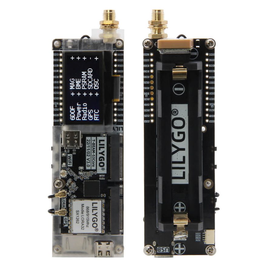
01 Hardware
| Vendor | LilyGO |
| PlatformIO env | tbeam-supreme |
| Board header | src/boards/tbeam_supreme.h |
| MCU | ESP32-S3FN8: 8 MB flash, 8 MB quad PSRAM |
| Chip family | ESP32-S3 |
| Radio | SX1262 in a socketed module (TCXO at 1.8 V, DIO2 drives the RF switch) |
| Display | 1.3" 128x64 SH1106 (I²C) — not the SSD1306 the other OLED boards carry |
| Extras | 18650 holder, AXP2101 PMU owning six rails, u-blox MAX-M10S or Quectel L76K GNSS, microSD, PCF8563 RTC, Qwiic socket; BME280 driven (temperature, humidity, pressure); QMI8658 IMU on SPI — driven, and faulty on the unit tested here: LilyGO's own example finds every other part on the board and cannot find this one either; QMC6310N magnetometer driven at 0x3c (heading, field strength and hard-iron calibration; uncorrected for tilt on this unit, whose accelerometer is faulty) |
| Host links | Wi-Fi access point + station · USB CDC-NCM Ethernet · native USB console |
| Flashing | hold BOOT while tapping RST |
02 Radio
| Transceiver | Semtech SX1262 |
| Radio family | SX126x |
| As the registry states it | SX1262 in a socketed module (TCXO at 1.8 V, DIO2 drives the RF switch) |
| TCXO | 1.8 V reference |
| DIO2 drives the RF switch | yes |
| Default channel | 869.525 MHz · BW 125 kHz · SF8 · CR 4/5 · 7 dBm inherited from Config.h |
| SPI bus | FSPI |
Every node on a channel must agree on frequency, bandwidth, spreading factor,
coding rate and sync word. These are the defaults this build ships with; they are changed
live on the node's settings page, which prints the matching RNodeInterface block.
03 Pin map
Read straight out of src/boards/tbeam_supreme.h — every peripheral
the firmware drives on this board, and the GPIO it drives it on. A harness diagram, not a
picture of where the parts sit.
Every pin as a table, with the define it comes from
| Peripheral | Signal | GPIO | Define | Note |
|---|---|---|---|---|
| Radio | SCK | GPIO 12 | PIN_LORA_SCK | |
| MISO | GPIO 13 | PIN_LORA_MISO | ||
| MOSI | GPIO 11 | PIN_LORA_MOSI | ||
| CS | GPIO 10 | PIN_LORA_CS | ||
| RST | GPIO 5 | PIN_LORA_RST | ||
| BUSY | GPIO 4 | PIN_LORA_BUSY | ||
| DIO1 | GPIO 1 | PIN_LORA_DIO1 | ||
| OLED panel | SDA | GPIO 17 | PIN_OLED_SDA | |
| SCL | GPIO 18 | PIN_OLED_SCL | ||
| microSD | SCK | GPIO 36 | PIN_SD_SCK | |
| MISO | GPIO 37 | PIN_SD_MISO | ||
| MOSI | GPIO 35 | PIN_SD_MOSI | ||
| CS | GPIO 47 | PIN_SD_CS | ||
| GNSS | RX | GPIO 9 | PIN_GPS_RX | |
| TX | GPIO 8 | PIN_GPS_TX | ||
| Power management | SDA | GPIO 42 | PIN_PMU_SDA | |
| SCL | GPIO 41 | PIN_PMU_SCL | ||
| IRQ | GPIO 40 | PIN_PMU_IRQ | ||
| Real-time clock | SDA | GPIO 42 | PIN_RTC_SDA | |
| SCL | GPIO 41 | PIN_RTC_SCL | ||
| IMU | CS | GPIO 34 | PIN_IMU_CS | |
| Controls & indicators | BTN | GPIO 0 | PIN_BUTTON |
04 Firmware support
What this build actually drives on this board. Where a part is fitted but left alone, the firmware's own reason is quoted underneath rather than summarised.
| Capability | State | Detail |
|---|---|---|
| Reticulum transport | driven | Path table, announce propagation, hop-by-hop forwarding |
| Wi-Fi AP + captive portal | driven | Status page, neighbours, bulletin board, settings |
| TCP 4242 + AutoInterface | driven | Stock RNS clients, zero-config discovery |
| LoRa radio | driven | Semtech SX1262 The transceiver is not soldered to this board: it is a plug-in module, which is why the rail that feeds it and the socket's own supply are separate entries in the rail map below. Electrically it is the same SX1262 as the T3-S3's and the T-Deck's — a TCXO on DIO3 at 1.8 V, DIO2 driving the antenna switch, no external amplifier — so the probe and every RF default apply unchanged |
| Radio self-test at boot | no | Proves the IRQ line on first boot |
| RF front end | no | Driven before the radio can hear anything |
| External PA | no | — |
| Display | driven | SH1106 OLED · 128×64 Same 128x64 geometry and the same GFX calls as every other OLED board here, and a different controller: the SH1106 has 132 columns of RAM with the panel wired to the middle 128, and no horizontal addressing mode. Driven by the SSD1306 code it comes up shifted by two columns, wrapping the last two, with an initialisation sequence it only partly understands. The address is not shared — see OLED_ADDR below. See src/ui/OledPanel.h |
| Backlight control | no | — |
| Touch layer | no | — |
| Keyboard | no | On its own microcontroller, over I²C |
| Trackball | no | — |
| microSD | driven | Reticulum store moves onto the card when one is present The card is on the second SPI host with the QMI8658's chip select beside it, and both are driven — they ask SpiBus for the same object rather than constructing one each, because two SPIClass objects on one host re-initialise the peripheral under each other (src/sys/SpiBus.h). BoardInit idles both selects before either driver starts, since the accelerometer's begin() runs first and a floating select is a device that may answer |
| GNSS | driven | 9600 baud LilyGO ship this board with either receiver and the same footprint, and nothing on the wire says which is fitted until it starts talking: both come up at 9600 baud speaking NMEA. So GPS_UBX stays off. A UBX frame sent to an L76K is a message that part has never heard of, and the only thing the binary protocol would buy here is a nap this board does not need it for — the PMU can cut the receiver's rail outright, which is what GPS_NAP derives to (Config.h) and a harder off than any message. If a unit is confirmed to carry the MAX-M10S, GPS_UBX 1 is the one line that changes, and it buys the UBX position and time frames rather than the nap. The unit this was brought up on *is* a MAX-M10S, confirmed the only way that counts: LilyGO's own example probes for an L76K, fails, and reports "UBlox GNSS init succeeded, using UBlox GNSS Module". That is a fact about one board and not about the model, which is exactly why the default here stays NMEA — a UBX default would break every L76K unit sold. One cost to know about that rail cut: the receiver's backup domain here is the AXP2101's own VBACKUP, which nothing names and nothing switches — and LilyGO's reference code for this board turns it off. So unlike the T-Beam, whose receiver keeps its almanac through a nap, a wake on this board should be assumed to be a cold start until a bench times one. Naming VBACKUP as a rail and enabling it is the fix if it matters, and it is worth a current measurement rather than an assumption |
| Real-time clock | driven | Seeds the system clock at boot The same part the ThinkNode M9 carries, at the same fixed address, on the PMU's pins rather than the general pair. It is what gives this board correct time indoors with no fix, where a board without one counts from 1970 until the sky clears — and it is fed from ALDO2, which is why that rail is on before anything asks the clock the time. Its interrupt is on GPIO 14 and nothing reads it |
| Power management IC | driven | — Six switched rails, of which five have to be on before the parts behind them exist as far as this firmware is concerned. The names are LilyGO's: ALDO1 the panel, the 6-axis part, the magnetometer and the BME280 ALDO2 the sensor bus itself and the PCF8563 — LilyGO's code notes this one cannot be turned off without losing the clock ALDO3 the transceiver module ALDO4 the GNSS receiver (off at power-up, and left off here) BLDO1 the microSD slot DCDC3 the module socket DCDC1 is the system rail this chip is powering the ESP32 from, so it is left alone: on the T-Beam it is the display's rail and gets switched on, and here switching it is switching the board off. LilyGO's pin poster (assets/image/T-BEAM-S3-Supreme.jpg) has the next two the other way round — "PMU SDA: IO41, SCL: IO42" — and it is wrong, which is worth writing down because it is the kind of error that cannot be half right: SDA and SCL are not interchangeable, and the AXP2101 and the clock both answer with them this way round. The same poster puts the RTC on the panel's bus at 17/18; the PCF8563 answers at 0x51 on this one. Take that poster for the parts list and this header for the wiring |
| Battery gauge | not driven | — The PMU is the battery reader on this board; there is no divider to sample |
| IMU | driven | QMI8658 The same part the ThinkNode M9 carries, wired to the card's SPI bus with a select of its own instead of to a shared I2C bus. That is a transport and not a different part: every register, the chip id and the configuration are the M9's, and only the three calls at the top of src/sys/Imu.cpp change (IMU_TRANSPORT). The bus and its three pins default to the card's, which is where they are — so the select is all this board has to name. Two consequences worth having written down. BoardInit idles this select *and the card's* before either driver exists, and depends on neither of them going first: a floating select is a device that may answer, and which begin() gets there first is a thing to get wrong rather than a thing to rely on — as an earlier draft of this comment did, naming the card, when main.cpp has Imu::begin() at 267 and sdCard.begin() at 277. And the part does *not* follow the screen here, unlike on the board that had one first: nothing on this board reads it for panel rotation, and the magnetometer that would want gravity from it is not suspended with the glass either, so its only readers are the console and the status API — which are asked with the glass dark as often as not. A derivation rather than a board opinion: IMU_FOLLOWS_SCREEN is DISPLAY_AUTO_ROTATE || (HAS_COMPASS && COMPASS_FOLLOWS_SCREEN), and the pair below sets the second half to 0 (Config.h, PeripheralPolicy.h). Turn COMPASS_FOLLOWS_SCREEN on and this follows it, which is the point of deriving it rather than stating it. The part is fitted on the unit this was brought up on and does not answer over SPI. Read that carefully, because two earlier versions of this comment got it wrong in opposite directions. The part is there: LilyGO's silkscreen names it, a chip sits under the name, and their wiki and pin poster both put a QMI8658 on the card's SPI bus at select 34. What it will not do is talk. What was measured, so nobody has to take it on trust: * the select works — GPIO 34 reads back what it is driven to, and it is the *only* pin that changes anything: 33, 48, 21 and 14 each leave MISO at its pull-up; * something is selected by it — MISO carries a stiff external pull-up and reads a hard 1 against an internal pull-down, and goes to a hard 0 the moment 34 is asserted, so a part is there and driving the line; * and it reads as zeroes. Every register in 0x00-0x0f, the status bytes, the temperature and 0x4d come back 0x00, but for a fixed 0x3e at the register-0 frame and 0x24 at the 0x0a frame — the same bits in all four SPI modes, at 1 MHz and at 100 kHz, and identical when the clock is bit-banged by hand instead of by the peripheral; * no write lands: CTRL1 written 0x40 reads back 0x00, and the vendor's own reset — 0xb0 into 0x60, then poll 0x4d for 0x80 — never completes; * and it is not power. Every AXP2101 rail was read back on the bench and then every one of them switched on, including the three LilyGO's init brings up and this firmware does not (BLDO2, DCDC4, DCDC5), and including their cold-boot power-cycle of the sensor rails. Not one byte changed. The framing is not the difference either: SensorLib's SPI transport sends `reg | 0x80` with the select low around it, which is this driver byte for byte, and their board init opens the same host on the same three pins with no enable line of its own. And that test has now been run. LilyGO's own QMI8658_GetDataExample, built from their repository with their board definition, their vendored SensorLib and their rail init — which power-cycles the sensor rails and brings up BLDO2, DCDC4 and DCDC5 — prints: Found QMC6310N MAG Sensor at address 0x3C Found OLED display at address 0x3D Found BME280 Sensor at address 0x77 Sd Card init succeeded, The current available capacity is 7.44 GB UBlox GNSS init succeeded, using UBlox GNSS Module Failed to find QMI8658 - check your wiring! Everything else on the board, found. The 6-axis part, not. So this is a hardware fault on this unit — the part or its joints — and not something a firmware change can reach. HAS_IMU stays 1 because the *board* carries the part and another unit's will answer; this driver reports the absence honestly, with the byte it read, which is all it can do |
| Magnetometer | driven | QMC6310 It is at 0x3c, on the panel's bus, and it reports chip id 0x80 in register 0 — a QMC6310, not the QMC6309 the M9 carries and not at any of the addresses that part uses. An earlier version of this header declared it absent on the strength of a scan that found nothing at 0x0d, 0x1c, 0x2c or 0x7c, which was the wrong conclusion from the right data: nobody had asked what the *third* answer on the panel's bus was. It is also, and this is worth writing down once, the device that made the panel look broken. Two addresses answered on that bus; 0x3c was taken for the panel, accepted an entire SH1106 initialisation and every frame after it without complaint — because a magnetometer's registers will take any write — while the glass, at 0x3d, kept the previous firmware's picture. It is driven, and the numbers it is driven with are not guesses. The part is known good on this unit before any of this firmware touched it: LilyGO's own QMC63xx_GetDataExample read it here and streamed sensible fields — about 123 uT total with a large offset on Z, which is what their calibration example exists for — in continuous mode at 200 Hz, 8 G, no oversampling. Those are the register values src/sys/QmcMag.h calls verified, and the counts that example printed beside its microtesla are the test vectors that pin this board's scale (test/test_qmc_mag). Two things about the reading on this board specifically. It is not levelled, and it says so. Tilt correction wants gravity from the accelerometer, and the 6-axis part above is faulty on this unit — so every reading here comes back with `levelled=false` and a heading computed as if the board were flat, which for a gateway bolted to a pole it very nearly is. A unit whose accelerometer answers gets the corrected heading with no change here. And it does not follow the screen. Nothing on this board's 128x64 pages shows a bearing: the readers are the console and the status API, which are asked of a dark node as often as not, so suspending the part with the glass would hand "asleep" to every caller it has. That is the same argument the accelerometer's own rule turns on, and it is stated once as a board fact rather than twice as a rule (COMPASS_FOLLOWS_SCREEN, PeripheralPolicy.h) — which also keeps IMU_FOLLOWS_SCREEN honest, since a compass that runs in the dark would otherwise hold up an accelerometer that had gone to sleep |
| Environment sensor | driven | BME280 Temperature, pressure and humidity, at 0x77: SDO is strapped high here, where the same part on another board is as likely to be at 0x76. It shares the panel's bus, which is why Environment::poll() is called from the main loop and from nowhere else — one reader on that bus is what keeps it safe (Environment.h, and issue 33 in the roadmap for the reason). This is the first sensor here that reports on the node's surroundings rather than on the node, and the first that does not follow the screen: a gateway on a pole reports the weather at the pole whether or not anybody is looking at its glass |
| Sounder | no | — |
| USB networking (CDC-NCM) | driven | The node is an Ethernet link with DHCP over the cable |
| PPP over the serial bridge | no | — |
05 Bench notes
verified on hardware 2026-09-08: SX1262 on air both ways (rx 24, tx 7 at 869.525, rssi -34, snr 12.5), AXP2101 found on its own I2C host and every rail it feeds alive — radio, panel, clock and card slot, microSD mounted (8 GB SDHC, Reticulum store moved onto it), PCF8563 holding time to a second, GNSS talking (932 sentences, no fix indoors), 8 MB of PSRAM free, the SH1106 panel rendering its pages and stepping through them on the button, and the BME280 reading 27.7 C, 60 % and 1012.7 hPa. The panel is at 0x3D, not the 0x3C that both its address probe and the RNode firmware point at: 0x3c is the QMC6310 magnetometer, which took an entire SH1106 initialisation without complaint because a register file accepts any write, while the glass kept the previous firmware's picture and every status field reported the display fine.
The three parts on that bus are now each identified by asking them — 0x3c magnetometer, 0x3d panel, 0x77 BME280 — The 6-axis part is fitted and does not answer: its select works and something drives MISO when it is asserted, but every register reads zero, no write lands, the vendor's reset never completes, and none of it changes across all four SPI modes, two clock rates, a hand-clocked control, or every rail the AXP2101 has. LilyGO's own QMI8658 example, built from their repository with their board definition and rail init, finds the magnetometer, panel, BME280, card and GNSS and then reports "Failed to find QMI8658 - check your wiring!" — so it is a hardware fault on this unit rather than anything a firmware change reaches.
Their magnetometer example does read the QMC6310N here, which is what made driving it a port rather than a research task — it is now driven by this firmware, whose register values and scale are the ones that example was running. Their GNSS probe identifies this unit's receiver as the u-blox MAX-M10S. USB composite with usb0 ready, Wi-Fi AP and transport online.
One thing the bench has not settled: whether a rail-cut GNSS nap costs a cold start here.
06 Install
Browser
Pick LilyGO T-Beam Supreme in the web flasher and click Install. Desktop Chrome or Edge, over HTTPS.
Terminal
pipx run --spec "git+https://github.com/dobrevit/RetiMesh_Node#subdirectory=tools/retimesh-flash" \
  retimesh-flash install --board tbeam-supreme
From source
pio run -e tbeam-supreme
pio run -e tbeam-supreme -t upload
pio run -e tbeam-supreme -t uploadfs