LilyGO T3-S3 with SX1280 + PA (2.4 GHz)
As t3s3-sx1280, but for the amplified module: the PA sits behind an RX/TX switch on GPIO 21/10 and the ceiling rises to 20 dBm. Flashing this image on a plain board would drive two GPIOs that board uses for something else, so pick by what is actually fitted.
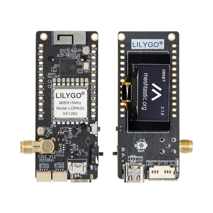
Shown here as the sub-GHz T3-S3; this build targets the same board carrying an SX1280 module instead.
01 Hardware
| Vendor | LilyGO |
| PlatformIO env | t3s3-sx1280-pa |
| Board header | src/boards/t3s3_sx1280_pa.h |
| MCU | ESP32-S3FH4R2: 4 MB flash, 2 MB PSRAM |
| Chip family | ESP32-S3 |
| Radio | SX1280 + PA |
| Display | 0.96" SSD1306 |
| Extras | microSD, battery ADC |
| Host links | Wi-Fi access point + station · USB CDC-NCM Ethernet · native USB console |
| Flashing | esptool can reset the chip through this port |
02 Radio
| Transceiver | Semtech SX1280 |
| Radio family | SX128x |
| As the registry states it | SX1280 + PA |
| DIO2 drives the RF switch | no |
| Default channel | 2445 MHz · BW 812.5 kHz · SF8 · CR 4/5 · 10 dBm set by this board's header |
| SPI bus | FSPI |
Every node on a channel must agree on frequency, bandwidth, spreading factor,
coding rate and sync word. These are the defaults this build ships with; they are changed
live on the node's settings page, which prints the matching RNodeInterface block.
03 Pin map
Read straight out of src/boards/t3s3_sx1280_pa.h — every peripheral
the firmware drives on this board, and the GPIO it drives it on. A harness diagram, not a
picture of where the parts sit.
Every pin as a table, with the define it comes from
| Peripheral | Signal | GPIO | Define | Note |
|---|---|---|---|---|
| Radio | SCK | GPIO 5 | PIN_LORA_SCK | |
| MISO | GPIO 3 | PIN_LORA_MISO | ||
| MOSI | GPIO 6 | PIN_LORA_MOSI | ||
| CS | GPIO 7 | PIN_LORA_CS | ||
| RST | GPIO 8 | PIN_LORA_RST | ||
| BUSY | GPIO 36 | PIN_LORA_BUSY | SX1280: not the SX1262's 34 | |
| DIO1 | GPIO 9 | PIN_LORA_DIO1 | SX1280 IRQ: not the SX1262's 33 | |
| RXEN | GPIO 21 | PIN_LORA_RXEN | ||
| TXEN | GPIO 10 | PIN_LORA_TXEN | ||
| OLED panel | SDA | GPIO 18 | PIN_OLED_SDA | |
| SCL | GPIO 17 | PIN_OLED_SCL | ||
| microSD | SCK | GPIO 14 | PIN_SD_SCK | |
| MISO | GPIO 2 | PIN_SD_MISO | ||
| MOSI | GPIO 11 | PIN_SD_MOSI | ||
| CS | GPIO 13 | PIN_SD_CS | ||
| Controls & indicators | BTN | GPIO 0 | PIN_BUTTON |
04 Firmware support
What this build actually drives on this board. Where a part is fitted but left alone, the firmware's own reason is quoted underneath rather than summarised.
| Capability | State | Detail |
|---|---|---|
| Reticulum transport | driven | Path table, announce propagation, hop-by-hop forwarding |
| Wi-Fi AP + captive portal | driven | Status page, neighbours, bulletin board, settings |
| TCP 4242 + AutoInterface | driven | Stock RNS clients, zero-config discovery |
| LoRa radio | driven | Semtech SX1280 Selects the SX1280 driver instead of probing. See LoRaRadio::begin() for why this cannot be auto-detected alongside the sub-GHz parts |
| Radio self-test at boot | driven | Proves the IRQ line on first boot One transmission at boot, timed against the TxDone interrupt. On a board whose IRQ pin is guessed wrong the chip still answers over SPI and still reports itself online, so nothing in an ordinary boot distinguishes a working radio from a deaf one. A transmit that never raises the interrupt takes the full 8 s timeout instead of tens of milliseconds, which does |
| RF front end | no | Driven before the radio can hear anything |
| External PA | driven | — The amplifier does not raise what the chip may be driven at — the SX1280 driver still refuses anything over 13 dBm — but it does raise what leaves the antenna. The operator has to account for the difference; the node only says an amplifier is fitted |
| Display | driven | OLED · 128×64 |
| Backlight control | no | — |
| Touch layer | no | — |
| Keyboard | no | On its own microcontroller, over I²C |
| Trackball | no | — |
| microSD | driven | Reticulum store moves onto the card when one is present |
| GNSS | no | — |
| Real-time clock | no | Seeds the system clock at boot |
| Power management IC | no | — |
| Battery gauge | no | — |
| IMU | no | — |
| Magnetometer | no | — |
| Environment sensor | no | — |
| Sounder | no | — |
| USB networking (CDC-NCM) | driven | The node is an Ethernet link with DHCP over the cable |
| PPP over the serial bridge | no | — |
05 Bench notes
builds only — never run on hardware, see below.
06 Install
Browser
Pick LilyGO T3-S3 with SX1280 + PA (2.4 GHz) in the web flasher and click Install. Desktop Chrome or Edge, over HTTPS.
Terminal
pipx run --spec "git+https://github.com/dobrevit/RetiMesh_Node#subdirectory=tools/retimesh-flash" \
  retimesh-flash install --board t3s3-sx1280-pa
From source
pio run -e t3s3-sx1280-pa
pio run -e t3s3-sx1280-pa -t upload
pio run -e t3s3-sx1280-pa -t uploadfs